 Products
 Projects
 Solutions
 Service
 News
News About CNC
 Contact Us
A single transformer failure can cost tens of thousands of dollars. A bayonet fuse is a critical, field-replaceable protective device used inside oil-filled distribution transformers to prevent such costly events. It stops faults before they destroy equipment.
This article covers what these fuses are, how they work, how to size them correctly, how to replace them safely, and how they fit into a complete transformer fuse protection strategy.
Understanding Bayonet Fuses
The Twist-and-Lock Mechanism
The fuse assembly has two main parts: a holder and a fuse link. The fuse link inserts directly into the transformer tank.
Its name comes from the bayonet mechanism, a twist-and-lock system that allows for quick, secure installation and removal.
This makes field work much faster. The design supports hot-stick operation and uses deadfront construction to keep linemen safe.
Expulsion Fuse Operation
At its core, a bayonet fuse is an expulsion-type fuse. When too much current flows through the circuit, the internal fusible element melts and turns to vapor. This creates an electrical arc.
The heat from that arc breaks down the surrounding oil and a special liner material inside the fuse, which produces a high-pressure gas. That gas bubble forcefully puts out the arc and stops the current flow.
Common Applications
While most people connect bayonet fuses with pad-mounted transformers, they are used in many medium-voltage settings.
- Pad-mounted distribution transformers
- Subsurface transformers
- Medium-voltage switchgear (up to 38kV)
- Wind turbine step-up transformers
Coordinated Protection Strategy
A bayonet fuse is rarely the only protective device on a transformer. Best practice calls for a “two-fuse” or “dual-fuse” setup for full transformer protection.
This system connects two fuses in series. The bayonet fuse clears low-level faults, such as secondary-side short circuits and sustained overloads. A backup fuse, usually a high-interrupting capacity current-limiting fuse, handles large faults like an internal winding failure.
This setup makes sure the right fuse operates for each type of fault, which is a key idea behind proper transformer fusing.
XRNT Current-Limiting Fuses for Transformer Protection
- Wide voltage range support from 12kV to 40.5kV
- Rated current capabilities up to 200A
- Quick-acting current-limiting interruption
- Perfect for high-voltage transformer protection

Correct Bayonet Fuse Sizing
Getting the size wrong is a serious mistake. A fuse rated too low will trip during normal startup currents, while a fuse rated too high will not protect the transformer from harmful overloads. Follow this simple three-step process for accurate sizing.
- Determine Transformer Full-Load Amperes (FLA). For a three-phase transformer, the formula is:
FLA = kVA / (Voltage_kV * 1.732). - Apply the Sizing Factor. Bayonet fuses must handle the temporary inrush current that flows when a transformer first powers up. Size them at 150% to 200% (1.5x to 2.0x) of the transformer’s FLA.
- Select the Next Standard Fuse Size. Once you calculate the required amperage, pick the next commercially available standard fuse rating that is equal to or greater than your calculated value.
A Worked Example
Let’s size a fuse for a 750 kVA transformer with a 12.47 kV primary voltage.
First, calculate the FLA: 750 / (12.47 * 1.732) = 34.7 Amps.
Next, apply a sizing factor of 1.5x: 34.7 A * 1.5 = 52.05 A. The next standard fuse size above 52.05A is typically a 65A fuse, so that would be the correct choice.
This process works across common voltage classes like 15kV, 25kV, and 38kV for transformers in the 75 kVA to 2500 kVA range.
Safe Replacement Procedure
This procedure reflects best practices from experienced field personnel. Follow every step with extreme caution.
Critical Safety First
WARNING: THIS PROCEDURE SHOULD ONLY BE PERFORMED BY QUALIFIED ELECTRICAL PROFESSIONALS WITH THE PROPER TRAINING AND PERSONAL PROTECTIVE EQUIPMENT (PPE).
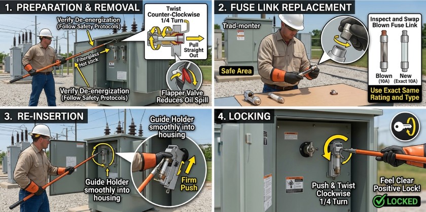
- Verify De-energization. Bayonet fuses are often load-break rated, meaning they can be opened while the transformer is live. However, many utility and site rules require the transformer to be de-energized first. Always follow your local safety protocols.
- Use a Hot Stick. Hook the eyelet of the bayonet fuse holder firmly with the right hot stick.
- Perform the “Twist-and-Pull” Action. Rotate the holder counter-clockwise about a quarter turn to unseat it, then pull it straight out of the housing. A flapper valve inside the housing will close to reduce oil spillage.
- Inspect and Replace the Fuse Link. Bring the assembly to a safe area. Open the holder and swap the blown fuse link for a new one of the exact same type and amperage rating. Using the wrong rating breaks the entire protection scheme.
- Re-insert the Assembly. Guide the holder back into the housing with a smooth, firm push. Push and twist clockwise until it locks in place. You should feel a clear, positive lock.
Fuses and Transformer Reliability
A fuse is built to fail on purpose so the transformer does not have to. That said, the true reliability of your system starts with the quality of the transformer itself.
Strong winding construction, high-grade insulation, and a solid tank are the first line of defense against the stresses that cause faults. High-quality transformers are built to meet or exceed industry standards like NEMA standards, so they can handle the demands of daily operation and fault conditions.
Conclusion
The bay-o-net fuse is a vital, field-serviceable part for overload and secondary fault protection in oil-filled transformers.
Correct sizing is not optional — it is required for the protection scheme to work. Safe replacement steps are just as important for the people doing the work. Mastering both areas keeps your equipment protected and your system running reliably.


