 Products
 Projects
 Solutions
 Service
 News
News About CNC
 Contact Us
Electric distribution substation construction is a structured engineering process. It turns high-voltage transmission or sub-transmission power into medium-voltage distribution power for homes, commercial buildings, and industrial users.
A typical substation project is not a short field job. It often takes 18 to 36 months from early planning to final energization. The work involves civil engineering, electrical design, protection systems, environmental control, safety management, and utility coordination.
A well-built distribution substation improves grid reliability. It also gives the local network enough capacity for future load growth.
Pre-Construction and Design
The success of a substation project is decided before construction begins. This phase turns load forecasts, reliability targets, land conditions, and utility standards into a buildable plan.
Good planning reduces cost risk. It also prevents rework during civil works, equipment installation, and commissioning.
| Phase | Main Work | Typical Focus |
|---|---|---|
| Pre-construction | Site selection, permitting, studies | Feasibility and risk control |
| Civil works | Grading, compaction, foundations | Physical construction base |
| Electrical installation | Equipment, buswork, cabling | System assembly |
| Testing | Equipment and relay checks | Safety verification |
| Energization | Step-by-step power-up | Operational readiness |
Site Selection and Permitting
Site selection is the first major decision. The site must support incoming lines, outgoing feeders, transformers, switchgear, access roads, and safe grounding.
Utilities usually compare several locations before choosing one. Early surveys may use 1:50,000 topographical maps, GPS mapping, and interconnection studies.
This preliminary assessment often takes three to four months. It can take longer if land acquisition, easements, or community concerns delay the project.
Engineers also check environmental and ground conditions.
Low-lying areas, marshy soil, riverbeds, and landslide-prone zones create higher foundation risk.
Soil drilling, groundwater checks, and soil resistivity tests help determine whether the site can support heavy equipment and a safe earthing system.
Permitting is another schedule risk.
In some jurisdictions, substation upgrades may require local building permits, zoning approval, and environmental review.
For example, California’s updated GO 131-E process introduced earlier consultation and a more streamlined permit-to-construct route for some utility projects.
Distribution-level installations below 50 kV may avoid formal CPUC discretionary permits, but they still need local coordination.
One-Line Diagram and System Studies
The electrical one-line diagram is the roadmap of the substation. It shows incoming lines, transformers, busbars, breakers, feeders, protection devices, and metering points.
This drawing defines the switching arrangement.
- A simple radial layout may serve rural or low-density loads.
- A single bus design gives moderate reliability, but a bus fault can de-energize all feeders.
- A two-transformer arrangement gives higher reliability because one transformer can continue supplying load if the other is out of service.
Before the design is finalized, engineers run several studies:
- Load flow studies check voltage levels and equipment loading.
- Short-circuit studies calculate fault current and confirm breaker interrupting capacity.
- Grounding studies verify that touch and step voltages remain within safe limits during faults.
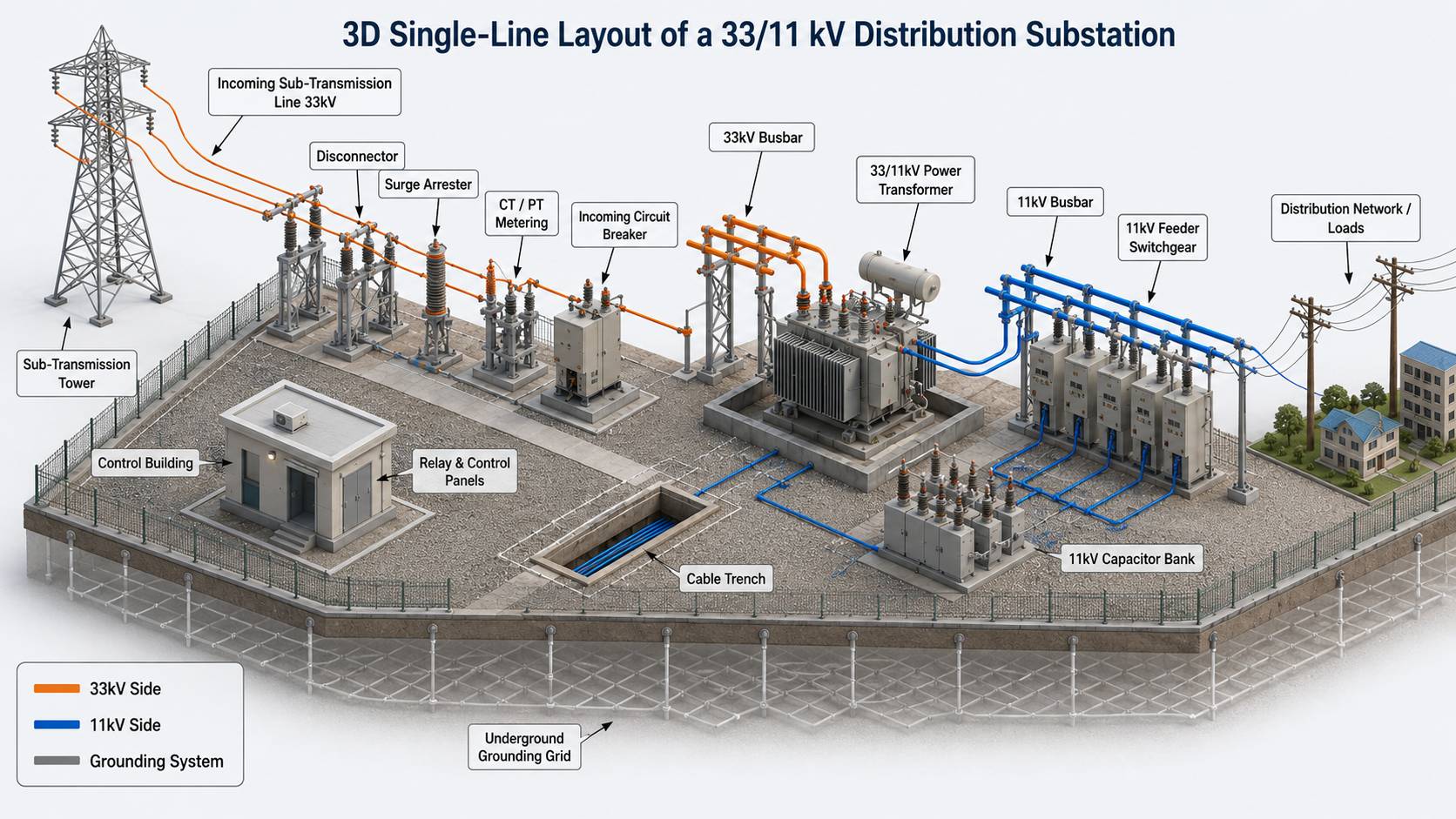
Physical Layout Design
The physical layout converts the one-line diagram into a real switchyard arrangement.
It places transformers, circuit breakers, disconnect switches, busbars, surge arresters, cable trenches, and the control building inside the fence.
The layout must provide electrical clearance. It must also allow crane access, maintenance vehicle movement, and future expansion.
Engineers may leave space for additional feeder bays or a future transformer.
This stage also decides whether the station uses air-insulated switchgear or gas-insulated switchgear.
AIS is common where land is available. GIS is preferred where land is expensive or space is limited.
Civil Works Phase
Civil works create the physical base for the substation. This phase includes clearing, grading, compaction, foundations, underground infrastructure, and structural steel.
Site Preparation
Site preparation begins after the work zone is fenced and secured. Crews clear vegetation, remove trees, and strip organic topsoil for later restoration.
The ground is then leveled through rough and fine grading. Final elevations are often controlled to within one-tenth of a foot. This precision supports drainage, equipment alignment, and foundation accuracy.
Soil compaction is critical. Heavy transformers and switchgear can settle if the subgrade is weak. Backfill is commonly placed in layers no thicker than 8 inches. Each layer may be compacted to at least 95% of maximum dry density, based on standard Proctor testing.
For remote sites, logistics are part of civil planning. Temporary camps may support 10 to 20 workers for 6 to 12 months. Access roads must support multi-axle transformer trucks and crane rigs.
Foundations and Steel Structures
Substation equipment requires reinforced concrete foundations. These foundations must withstand static loads, vibration, wind, seismic forces, and soil movement.
During concrete work, crews install embedded sleeves, anchor bolts, conduits, and grounding connection points.
Transformer foundations often include oil containment basins. These basins help control spills from mineral insulating oil.
Steel erection begins after the concrete reaches its required strength. Crews assemble columns, gantry towers, equipment stands, and bus supports.
A medium-sized substation can require about 13,000 kg of structural steel and more than 25,500 bolts.
Grounding Grid and Surface Layer
The grounding grid is one of the most important safety systems in the substation.
It gives fault current a low-impedance path into the earth. It also limits dangerous touch and step voltages.
A typical ground grid uses 4/0 AWG bare annealed copper conductors. These conductors are installed in an orthogonal mesh pattern.
A common minimum burial depth is 600 mm, or 24 inches, below grade.
The surface layer also affects safety. Many switchyards use 100 to 150 mm of clean crushed rock.
This gravel layer improves drainage, limits vegetation, and increases surface resistance. Higher surface resistance helps reduce touch and step voltage risk during faults.
Where asphalt is used in urban substations, engineers add test wells. These wells allow annual grid resistance testing because asphalt seals the ground surface.
Underground Infrastructure and Control Building
Before major equipment is installed, workers place duct banks, conduits, cable trenches, and manholes. These systems carry power, control, protection, communication, and instrumentation cables.
The control building is the operating center of the substation. It houses protection relays, SCADA equipment, communication gateways, AC service panels, DC battery systems, and auxiliary controls.
The DC battery system is critical. It powers relays and breaker trip coils when AC station service is unavailable.
Battery rooms may require fire-rated doors, acid-resistant floors, and ventilation to prevent hydrogen buildup.
Key Equipment in a Distribution Substation
A distribution substation works as a coordinated system. Each device has a defined role in power transformation, protection, switching, measurement, and control.
Power Transformers
The power transformer is the main asset in a distribution substation. It steps down higher voltage power to a distribution voltage that can feed local circuits.
Transformers are usually the heaviest and most expensive components on site. Their installation requires heavy transport, crane lifting, foundation alignment, and oil containment planning.
Large oil-filled transformers need careful fluid processing. During vacuum oil filling, crews remove moisture and trapped air from the insulation system.
A common process holds the transformer under deep vacuum for at least 4 hours. After filling, the transformer may stand for 24 to 48 hours so micro-bubbles can dissipate.
Circuit Breakers and Disconnect Switches
Circuit breakers interrupt fault current. They protect transformers, buses, and outgoing feeders when relays detect a short circuit or other abnormal condition.
Breakers are designed to extinguish the arc created during current interruption. Common technologies include vacuum, oil, and SF6 gas.
Disconnect switches provide visible isolation. Crews use them to confirm that equipment is disconnected before maintenance.
They are not intended to break load current. They should operate only after a breaker has opened the circuit.
Busbars, Conductors, and Surge Arresters
Busbars connect the main equipment inside the substation. They may be rigid aluminum or copper tubes, or flexible stranded conductors.
Surge arresters protect equipment from lightning and switching surges.
Under normal voltage, they remain inactive.
During a surge, they provide a low-resistance path to ground and divert harmful energy away from transformers and switchgear.
Instrument Transformers and Protection Systems
Current transformers and voltage transformers reduce high primary values into safe secondary signals.
Protection relays, meters, and SCADA systems use these signals to monitor the grid.
Protection systems must be reliable and selective. Many substations use redundant protection schemes.
Group A and Group B relays may use separate panels, separate CT cores, separate DC supplies, and separate breaker trip coils.
This design reduces the chance that one failure disables all protection.
Electrical Installation Phase
After civil work and foundations are complete, electrical installation begins. This phase brings the substation equipment together as one operating system.
Major Equipment Installation
Transformers, breakers, switchgear, surge arresters, and instrument transformers are moved from the staging area to their foundations.
Alignment must be precise. GIS equipment, for example, may require millimeter-level alignment before modules are connected.
After assembly, GIS gas compartments are evacuated and filled with high-purity SF6 gas.
Buswork and High-Voltage Connections
Crews install overhead conductors, rigid bus pipes, insulators, clamps, and terminal connectors.
Bolted joints are tightened to the specified torque. Welded bus sections must be completed correctly to avoid hot spots.
Poor connections create heat. Heat can damage terminals, reduce equipment life, and cause outages.
Control Cable Installation
Control, protection, power, communication, and instrumentation cables are pulled through trenches, ducts, and trays. These cables connect field equipment to relay panels and SCADA systems.
Cable routing must reduce electromagnetic interference. Power cables should be separated from control and communication cables. Shielded CT and VT circuits are often grounded at one end to avoid ground loops during ground potential rise events.
Each cable must be labeled, terminated, tested, and recorded on as-built drawings. This work is time-consuming, but accuracy is essential. A wrong termination can cause a relay to trip the wrong breaker or fail to trip during a fault.
Testing and Commissioning
Construction is not complete until the substation proves it can operate safely. Commissioning turns a built facility into a working utility asset.
Pre-Commissioning Tests
Pre-commissioning is performed before primary circuits are energized. It includes insulation resistance tests, transformer checks, breaker timing tests, CT and VT tests, cable continuity tests, and grounding inspections.
CT testing may include polarity checks with a 1.5 V battery, ratio testing, insulation resistance measurement, and magnetization tests at 25%, 50%, 75%, and 100% of knee point voltage.
Ground grid continuity is also verified. Some tests use a 100 to 300 A high-current source with a four-wire Kelvin meter to confirm low-resistance bonds between equipment frames, neutrals, and structures.
Protection, SCADA, and Functional Checks
After individual equipment passes inspection, integrated systems are tested. Engineers inject secondary current and voltage into relays. They confirm trip logic, interlocks, alarms, and breaker operation.
SCADA point-to-point checks verify that status signals, analog values, alarms, and control commands are mapped correctly.
Time synchronization is also checked, especially in substations that use digital relays or IEC 61850 communication.
Energization Sequence
Energization is a controlled procedure. It requires coordination between field teams, utility dispatchers, and interconnecting parties.
The sequence starts with a final walkdown. Teams remove temporary grounds, tools, ladders, and lockout devices. Then DC control power and AC auxiliary power are energized. This ensures that relays, alarms, and trip circuits are active before high voltage is applied.
Next, the incoming line, primary bus, and transformer are energized. The transformer may remain under no-load conditions for a 24-hour soak period. Operators monitor sound, oil level, gas level, cooling fans, alarms, and relay indications.
After the no-load checks pass, outgoing feeders are energized step by step. Engineers monitor load current, phase angle, relay readings, and SCADA telemetry. The goal is to confirm that CT and VT polarities are correct and that the substation can carry load safely.
Environmental Protection and Safety
Distribution substations contain oil-filled equipment, live electrical systems, and critical grid assets. Environmental and safety measures must be built into the project.
In the United States, EPA SPCC rules require secondary containment when aggregate oil storage exceeds 1,320 gallons. A containment system is commonly sized for 100% of the largest transformer oil volume, plus an additional 10% margin for stormwater.
Gravel-filled containment basins must account for stone void space. Clean crushed rock may provide about 40% void space. This affects the required basin depth and area.
Site safety is equally important. Construction teams manage arc flash risk, step potential, lifting hazards, fall hazards, and live-line boundaries. Daily job hazard analyses and clear stop-work authority help prevent incidents during high-risk work.
More Than Construction
Electric distribution substation construction combines planning, civil works, electrical installation, protection engineering, and commissioning.
The final asset is more than steel, copper, concrete, and transformers. It is a controlled power delivery node. When designed and built correctly, it supports safer operation, faster fault isolation, reliable feeder service, and long-term grid growth.


