 Products
 Projects
 Solutions
 Service
 News
News About CNC
 Contact Us
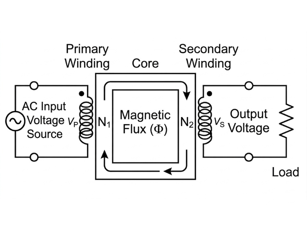
A transformer wiring diagram is the blueprint for every safe and efficient electrical installation involving an electrical transformer. It shows you exactly how all the parts should be connected. Think of it as a map. It shows you where the input voltage connects, how the internal windings are arranged, and where the output voltage is delivered to the load.
Below is a simple breakdown of a basic single-phase transformer electrical diagram. Picture two coils of wire with a block in the middle. On the left, you have the Primary Winding, which connects to your Input Voltage source. On the right is the Secondary Winding, which delivers the transformed Output Voltage to your load. The block in the middle represents the Core, which moves magnetic energy between the windings.
Understanding this basic layout is the first step toward reading any transformer schematic. These diagrams are not just suggestions — they are critical instructions. Following a proper transformer connection plan keeps the equipment working as designed, prevents damage from short circuits, and, most importantly, keeps people safe.
Transformer Wiring Quick-Reference
Interactive Connection Guide for Industrial & Control Applications
| Connection | Wiring Key |
|---|---|
| Delta-Wye (Δ-Y) | Delta Primary / Wye Secondary with Neutral |
| Delta-Delta (Δ-Δ) | Closed loop; Reliable for industrial power |
| Series | Jumper X2-X3; Use X1-X4 for full voltage |
| Parallel | Jumper X1-X3 & X2-X4 for max current |
Transformer Anatomy and Symbols
To read diagrams correctly, you first need to know the parts they show. Every transformer, from a small control unit to a large power transformer, shares a few key parts.
Here are the core components you will find in a transformer circuit:
- Primary Winding: This is the coil that connects to the power source. It’s the “input” side of the transformer.
- Secondary Winding: This coil connects to the load and provides the stepped-up or stepped-down voltage. It’s the “output” side.
- Iron Core: Made of layered steel sheets, the core focuses the magnetic field and allows energy to move efficiently from the primary to the secondary winding.
- Terminals/Bushings: These are the physical connection points for the windings. On diagrams, they are labeled with codes like H1 and H2 for the high-voltage (primary) side and X1, X2 for the low-voltage (secondary) side.
In a transformer wiring diagram, these physical parts are shown using standard symbols so everyone reads them the same way. Using these standardized symbols in electrical diagrams is a basic practice in electrical work.
| Symbol | Meaning |
|---|---|
(~~~) |
Represents a winding or coil. Two parallel coils are shown. |
││ |
Two or more vertical lines between windings, indicating an iron core. |
─┴─ |
The symbol for a chassis or earth ground connection. |
H1, H2 |
Labels for the primary (high-voltage) terminals. |
X1, X2 |
Labels for the secondary (low-voltage) terminals. |
Knowing these parts is key, but the quality of the transformer itself determines how well it performs and how safe it is. For industrial uses that need strong step-up, step-down, or isolation transformers, looking at professionally built options is an important next step.
Essential Connection Concepts
Beyond just spotting parts on a diagram, a technician must understand the rules that control a transformer connection. Polarity, ratio, and taps are three ideas that decide how a transformer will behave in a circuit.
Understanding Polarity
Transformer polarity refers to the direction of the voltage produced between the high-voltage and low-voltage terminals. It is set by the direction the coils are wound relative to each other.
Polarity is either additive or subtractive. This becomes critically important when connecting multiple transformers in parallel to increase capacity.
If two transformers are connected in parallel with mismatched polarity, it creates a severe short circuit the moment the bank is turned on. We always check polarity markings — usually a dot or an “X1″ marker — before turning on any new parallel setup. It’s a quick check that stops major damage.
Voltage Ratios
The ratio of turns between the primary and secondary windings decides whether a transformer is step-up or step-down. A step-up transformer has more turns on its secondary winding than its primary, which gives a higher output voltage. A step-down transformer has fewer turns on its secondary, which gives a lower output voltage.
This relationship is defined by a simple formula: Vp/Vs = Np/Ns.
Here, Vp is the primary voltage, Vs is the secondary voltage, Np is the number of turns on the primary winding, and Ns is the number of turns on the secondary winding. This ratio is the core idea behind how transformers work.
Transformer Taps
Taps are extra connection points on a transformer’s winding. They allow for small changes to the turns ratio.
This feature helps correct for high or low line voltage, keeping the secondary output within the range you need. A multi-tap transformer is flexible, which is why it is common in places where the input voltage is not always steady.
Transformer Single-Phase Wiring
Single-phase transformers are the most common type found in homes, businesses, and light industrial settings. Their wiring is generally simple, but you must be precise.
Basic Single-Voltage Connection
Let’s look at a standard step-down example, such as converting a 240V source to a 120V load. The transformer wiring diagram will guide you through a simple three-step process.
- Safety First: Always turn off and lock out the power source before making any connections. Use a multimeter to confirm the circuit is dead.
- Primary Connection: Connect the primary terminals, labeled H1 and H2, to the incoming 240V supply lines.
- Secondary Connection: Connect the secondary terminals, labeled X1 and X2, to the 120V load.
This is the most basic transformer connection and forms the base for more complex setups.
Dual Voltage Connections
Many control transformers come with two windings on the secondary side to give multiple voltage options from one unit. For example, a transformer might have two 120V secondary windings that can be wired for either 120V or 240V output.
To get a 240V output, the two secondary windings are connected in series. You do this by connecting terminal X2 of the first winding to terminal X3 of the second winding. The load is then connected across X1 and X4.
To get a 120V output with double the current capacity, the windings are connected in parallel. This means connecting X1 to X3 and X2 to X4. The load is then connected across the X1/X3 pair and the X2/X4 pair.
| Connection Type | Jumper Configuration | Resulting Output (for a 120/240V secondary) |
|---|---|---|
| Series | Connect X2 to X3 | 240V across X1 and X4 |
| Parallel | Connect X1 to X3; Connect X2 to X4 | 120V across X1/X3 and X2/X4 |
These standard single-phase transformer connections are basic skills for any electrician or technician. Always check the manufacturer’s diagram, since terminal labels can vary.
Transformer Three-Phase Connections
For industrial and large commercial settings, three-phase power is the standard because it runs large motors and heavy machines efficiently. So, understanding three-phase transformer connections is a key skill for working in these places.
The two main methods for connecting three-phase transformers are Wye (Y) and Delta (Δ).
The Wye (Y) Connection
A Wye, or Star, connection is made by joining one end of each of the three transformer windings to a shared point. This shared point is called the neutral.
The key feature of a Wye connection is that it provides two different voltages. You can draw power line-to-line (e.g., 480V) or line-to-neutral (e.g., 277V). This makes it very useful for buildings that need to power both three-phase machines and single-phase lights or outlets from the same service. A Wye transformer wiring diagram will clearly show the “Y” shape and the central neutral point.
The Delta (Δ) Connection
In a Delta connection, the three windings are connected end-to-end in a closed loop, forming a triangle shape like the Greek letter Delta, Δ. A Delta setup does not have a neutral point.
Its main strength is reliability. If one of the three windings in a Delta bank fails, the remaining two can keep supplying three-phase power in an “open Delta” setup, though at a reduced capacity of about 58%. This toughness matters a lot in industrial processes where shutdowns are costly.
Common Configurations
Transformers are often connected with different primary and secondary setups to meet specific needs. A Delta-Wye (Δ-Y) connection is very common. It takes a high-voltage Delta primary, which doesn’t need a neutral, and steps it down to a lower-voltage Wye secondary that provides a neutral for single-phase loads.
Other setups like Wye-Delta, Wye-Wye, and Delta-Delta are used for different needs, each with its own strengths related to voltage stability, harmonic control, and fault handling. For a deeper look, review these resources on three-phase transformer models and connections.
Choosing between Wye and Delta depends heavily on the power needs and fault tolerance of the application. This choice goes hand-in-hand with picking a transformer built for the demands of three-phase systems.
Safety and Troubleshooting
A transformer wiring diagram guides you toward a correct installation, but experience and a focus on safety are what prevent accidents. No task matters more than making sure the circuit is safe before, during, and after a transformer connection.
Pre-Connection Safety Checklist
Before a single wire is connected, run through a required safety checklist.
- Always de-energize and apply a lock and tag (LOTO) to the power source. There are no exceptions.
- Use a calibrated multimeter to confirm that the input voltage matches the transformer’s primary rating.
- Visually check the transformer for any signs of physical damage, such as a cracked casing, leaking oil, or damaged terminals.
- Make sure a proper grounding connection is in place according to the transformer electrical diagram and local electrical codes. A solid ground is a critical safety component.
Troubleshooting Common Issues
Even with careful work, problems can come up. Here are some of the most common issues found in the field and their likely causes.
- Problem: No Output Voltage
- Possible Causes: Input voltage is not present (check breaker/fuse), a loose connection on the primary side, an internal primary fuse is blown, or the primary winding has failed.
- Problem: Incorrect Output Voltage
- Possible Causes: The wrong taps were used for the given input voltage, or the windings on a dual-voltage secondary are wired incorrectly, such as in series when they should be in parallel.
- Problem: Transformer Overheating
- Possible Causes: The secondary is overloaded beyond its kVA rating, there is not enough airflow around the transformer, or there is an internal short circuit causing too much current.
For serious faults, the transformer’s build quality and its ability to withstand short circuit forces are put to the test. A well-built transformer can often survive faults that would destroy a cheaper one.
From Diagram to Success
We have gone from reading basic symbols to understanding the details of three-phase connections. Each step builds on the last, showing the logical and step-by-step nature of electrical work.
A transformer wiring diagram is far more than a simple drawing. It is a communication tool, a safety guide, and a plan for success. Whether you are wiring a simple control transformer circuit or a complex industrial bank, this document is your most valuable asset.
Approach your next project with the confidence that comes from knowledge, the care to check every transformer connection, and a firm commitment to putting safety first.


