 Products
 Projects
 Solutions
 Service
 News
News About CNC
 Contact Us
-
Product Overview
-
Product Details
-
Data Download
-
Related Products


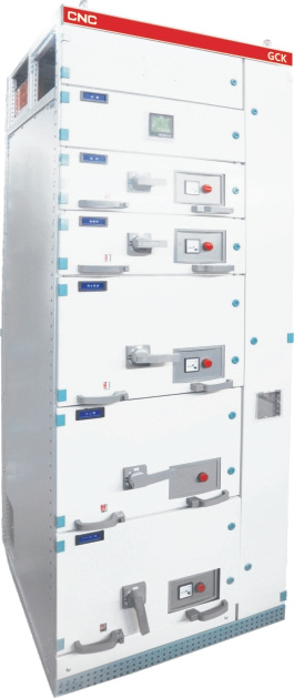
GCK Low-voltage Switchgear Panel, Withdrawable Type
Application: mainly applicable in places with high automation and need to communicate with computer, like large power station and petrochemistry system, as the low voltage distribution device of the distribution and motor controling, and reactive power compensation in power system.
Protection degree: IP30, IP40. Bus type: three phase four wires, three phase five wires. Operation type: in-place, long-distance and automatic.
Standard: IEC60439-1
Conatct Us
Product Details
Selection
Operating conditions
1. Ambient air temperature: -5℃ ~+40℃ . Daily average temperature: ≤35℃.
When the actual temperature exceed the range, it should be used by reducing the capacity accordingly.
2. Transport and store temperature: -25℃ ~+55℃ . do not exceed +70℃ in short time.
3. Altitude: ≤2000m.
4. Relative humidity : ≤50%, when temperature is +40℃.
When temperature is low, larger relative humidity is allowed. when it is +20℃, relative humidity can be 90%. Since the temperature change will make out condensation.
5. Installation inclination: ≤5%
6. Applicable in the places without corrosive and flammable gas. Note: Customized products are available.
Technical data
1. Electric datas
1) Rated insulation voltage: 690V/1000V
2) Rated operational voltage: 400V/690V
3) Rated frequency: 50/60Hz
4) Rated impulse withstands voltage: 8kV
5) Rated voltage of auxiliary circuit: AC380/220V, DC110/220V
6) Over-voltage grade: III
7) Rated current: ≤5000A
8) Rated current of horizontal bus bar: ≤5000A
9) Rated current of vertical bus bar: 1000A
2. Mechanical items
1) Incoming and outgoing mode
2) Cable incoming and outgoing
3) Connection mode
4) The functional units completely separated or partially separate
Feature
GCK panel is combination structure with bolt. The complete panel is compose of door, terminal board , baffle plate ,supporting frame and drawer, busbar, etc.
Basic frame adopts FA28 type or KB type (Ctype) to combine with together. Total structural components of frame are connected by self-tapping screw.
It should add to door, face place, baffle plate, supporting frame and drawer to finish completed panel by requirements.
The installation hole of body and components modules E=25mm change,flexible and convenient to install.
Drawer unit height divide into ½ unit, 200mm, 300mm, 400mm, 500mm, and 600mmm series. The loop current decide the drawer height,virtual installation height is 1800mm.
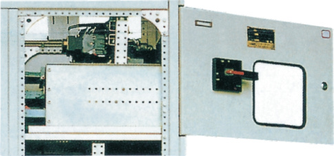
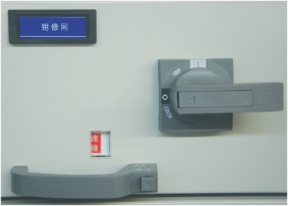
GCK panel withdrawable function unit adopts special push (pull) mechanism, light structure, perfect interchange. It indicate of working position, test position and isolating position mechanical locking condition. Install additional pad lock for operating handle.
The frame and inner metal components are galvanized to assure reliable earthing.
GCK basic frame is combination assembly type structure, adopt standardized module design. for combination assembly type structure, the standard module design.
Compact structure, flexible assembly, can be assembled into a protection, measurement and control, indicating etc. standard unit, Can choose assembly according to requirement, To form different frame Features and drawer unit.
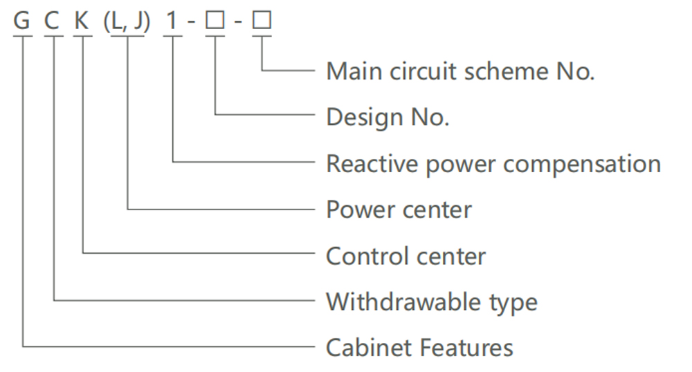
1. The cabinet frame
C type material adopted for the mainframe, Frame parts and Special parts will be provided by our company to make sure the accuracy and quality.
● Parts forming size, hole size,Equipment interval adopt modularization. (E=25mm)
● The internal structure should be galvanized.
● The top cover is detachable,horizontal bus can be installed easily after removing the top cover, Hand ring
● External phosphating treatment; Then use electrostatic epoxy powder coating.
● Cabinet frame is divided into the busbar compartment, functional compartment, the cable compartment three separate interval, Can prevent accidents diffusion and convenient charged repair.
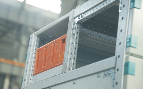
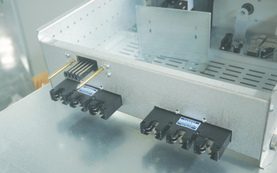
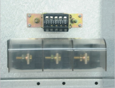
2. Functional unit (Withdrawable part)
● Functional unit: Feeder unit , Motor unit,utility power unit.
● The high modulus of drawer unit is 200mm, include 1/2unit,1unit,2 unit,3 unit four size series.
Unit loop rated current below 630A.
● Each MCC Cabinet can install 9 set drawer with 1 unit , or 18 set drawer with ½ unit.
● The compartment door plate is interlocked between operating mechanism and drawer, the door can be open until the main switch is on the close position.
● The main switch operating mechanism can be locked in close or open position by a padlock , the equipment can be maintained safely.
● There are main circuit outlet plug,auxiliary circuit secondary plug and earthing plug at the back of function unit.
● The earthing plug make sure the protection circuit continuity when drawer on Separation tests connection position.
● Functional unit compartment by metal partition board.
● Compartment valve, can be open and close automatically, with drawers pushed and pulled so that in the compartment without touching the vertical busbar.
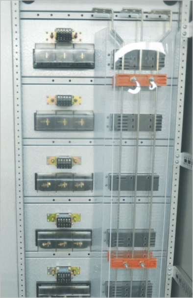
3. Busbar system
● Vertical bus uses polycarbonate engineering plastic shell sealed.
● GCK, GCL busbar system use 3P4W, 3P5W, Horizontal busbar will be installed at the top of cabinet, N phase, PE phase. Can be installed on the top of the cabinet, and can also be arranged in the cabinet bottom.
Overall and mounting dimensions(mm)
The effective height of installation
1. Electric cabinet and buscouple cabinet
Cabinet width can be 600,800,1000,1200,(800-400)mm according to rated current and method of incoming and outgoing.
Depth of cabinet is 800,1000(Advise to use 1000mm ,The top incoming and top outgoing must be 1000mm)
2. Feeder cabinet
Cabinet Width: 600, 800mm
Cabinet depth: 600, 1000 (advise to use 1000mm top outgoing cabinet must be 1000mm)
3. Motor control cabinet
Width: 600, 600+200mm
Depth of cabinet: 800, 1000mm(advise to use 1000mm top outgoing cabinet must be 1000mm)
Power compensation cabinet
Width: 600(4, 6 loop), 800(8), 1000(10 loop )mm cabinet depth: 800, 1000mm
| Rated current (A) | Copper bus model (mm) |
| 630 | 50 ×5 |
| 1250 | 60 × 10 |
| 1600 | 80 × 10 |
| 2000 | 100 × 10 |
| 2500 | 2(80 × 10) |
| 3150 | 2(100 × 10) |
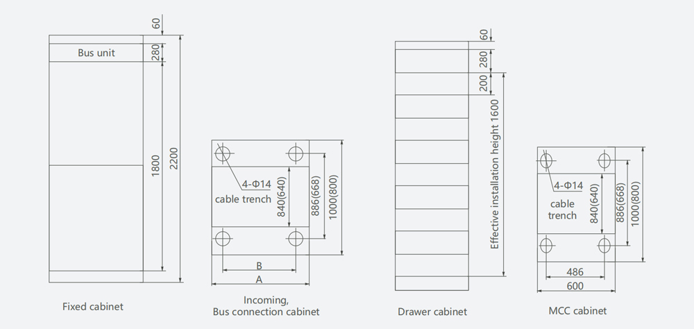
| Item | A | B |
| Electric power or Electric feeder | 600 | 486 |
| Electric power or Bus connection | 800 | 686 |
| Electric power or Bus connection | 1000 | 886 |
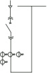
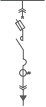
Main single line diagram
Sheet 2
| Program No. | 01 | 02 | 03 | 04 | 05 | 06 | 07 |
| Single line diagram | 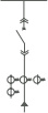 |
 |
/ | ||||
 |
|||||||
| Application | Overhead power | Cable power | Buscouple | / | |||
| Rated current (A) | 630~1600 | 2000~3150 | 630~1600 | 2000~3150 | 630~1600 | 2000~3150 | / |
| Circuit breaker | ME630~ME3205, AH6B~AH30C, M08~M32, YCW1-2000, YCW1-3200 / | ||||||
| Current transformer | LMK-0.66 □/5 / | ||||||
| Cabinet width(mm) | 800 | 1000 | 800 | 1000 | 800 | 1000(1200) | / |
| Small compartment height(mm) | 1800 | 1800 | 1800 | 1800 | 1800 | 1800 | / |
| Instruction | When the rated current exceeds 3150A, the user should consult with the manufacturer. | ||||||
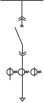
Continued Sheet 2
| Program No. | 08 | 09 | 10 | 11 | |||||||
| Single line diagram |
|
|
|
 |
|||||||
| Application | Electric feeder | Electric feeder | Electric feeder | Electric feeder | |||||||
| Main electrical
components |
Circuit breaker | ME630~ME1000
M08~M10 YCW1~2000 |
YCM1-100 YCM1-250 | TO-400B YCM1-400 YCM1-400 | QSA-63 QSA-125 | QSA-250 QSA-400 | QSA-630 | ||||
| Current transformer | LMK-0.66 | LMK-0.66 | LMK-0.66 | LMK-0.66 | LMK-0.66 | LMK-0.66 | |||||
| Cabinet width(mm) | 600 | 600 | 600 | 600 | 600 | 600 | |||||
| Small compartment height(mm) | / | 200 | 300 | 400 | 600 | 200 | 300 | 400 | 600 | 600 | |
| Instruction | Each set can install two loops | The number of measuring transformer is selected according to the practical situation | |||||||||
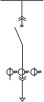

| Program No. | 12 | 13 | ||||||
| Single line diagram | 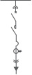 |
 |
||||||
| Application | Motor control | Motor control | ||||||
| lectrical
nents |
Circuit breaker knife fuse switch | TG-30B | TG-100B | TG-225B | TG-225B | QSA-63 | QSA-125 | QSA-125 |
| CM1-63 | CM1-100 | CM1-225 | CM1-225 | / | / | / | ||
| YCM1-100 | YCM1-100 | YCM1-225 | YCM1-225 | / | / | / | ||
| in e
mpo |
Contactor | B9-B45 | B45-B85 | B105-B170 | B250 | B9-B45 | B45-B85 | B105-B170 |
| Ma
co |
Thermal relay | T16-T45 | T45-T105 | *T16 | C | T16-T45 | T16-T45 | *T16 |
| Current transformer | LMK-0.66 | LMK-0.66 | LMK-0.66 | LMK-0.66 | LMK-0.66 | LMK-0.66 | LMK-0.66 | |
| Cabinet width(mm) | 600 | 600 | 600 | 600 | 600 | 600 | 600 | |
|
Small compartment height(mm) |
200 | 200 | 400 | 600 | 200 | 200 | 400 | |
| Instruction | ≤11KW | ≤30KW | ≤55KW | ≤105KW | ≤15KW | ≤30KW | ≤55KW | |
| According to each cabinet circuit number, the appliance should consider the heating capacity
* adopt current transformer protection. 7.5KW and below can also adopt 1/2 unit. |
||||||||
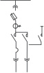
| Program No. | 14 | 15 | |||
| Single line diagram | 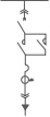 |
/ | |||
| Application | Motor reversible control | / | |||
| lectrical
nents |
Circuit breaker knife fuse switch | TG-30B | TG-100B | TG-225B | / |
| CM1-63 | CM1-100 | CM1-225 | / | ||
| YCM1-100 | YCM1-100 | YCM1-225 | / | ||
| in e
mpo |
Contactor | B9-B45 | B45-B85 | B105-B170 | / |
| Ma
co |
Thermal relay | T16-T45 | T45-T105 | *T16 | / |
| Current transformer | LMK-0.66 | LMK-0.66 | LMK-0.66 | / | |
| Cabinet width(mm) | 600 | 600 | 600 | / | |
|
Small compartment height(mm) |
200 | 200 | 400 | / | |
| Instruction | ≤11KW | ≤30KW | ≤55KW | / | |
| According to each cabinet circuit number, the appliance should consider the heating capacity
* adopt current transformer protection. 7.5KW and below can also adopt 1/2 unit. |
|||||
| Program No. | 16 | 17 | |||||
| Single line diagram | 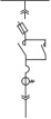 |
 |
|||||
| Application | Motor reversible control | Y-Δ Motor control | |||||
| ical | Knife fuse switch | QSA-63 | QSA-125 | QSA-250 | QSA-63 | QSA-125 | QSA-250 |
| ectr
one |
Contactor | B9-B45 | B45-B85 | B105-B170 | B9-B45 | B45-B85 | B105-B170 |
|
in el mp |
Thermal relay | T16-T45 | T45-T105 | *T16 | T16-T45 | T45-T105 | *T16 |
| Ma
co |
Current transformer | LMK-0.66 | LMK-0.66 | LMK-0.66 | LMK-0.66 | LMK-0.66 | LMK-0.66 |
| Cabinet width(mm) | 600 | 600 | 600 | 600 | 600 | 600 | |
|
Small compartment height(mm) |
200 | 300 | 600 | 300 | 400 | 600 | |
| Instruction | ≤15KW | ≤30KW | ≤55KW | ≤15KW | ≤30KW | ≤55KW | |
| According to each cabinet circuit number, the appliance should consider the heating capacity
* adopt current transformer protection. |
|||||||
| Program No. | 18 | 19 | ||||||||||
| Single line diagram | 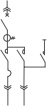 |
 |
||||||||||
| Application | Y-Δ Motor control | Power supply change over | ||||||||||
| Main electrical
omponents |
Circuit breaker |
TG-30B | TG-100B | TG-225B | ME630~1000A | |||||||
| CM1-63 | CM1-100 | CM1-225 | AH600~1000A | |||||||||
| YCM1-63 | YCM1-100 | YCM1-225 | M800~1000A | |||||||||
| YCW1-2000 | ||||||||||||
| Contactor | B9-B45 | B45-B85 | B105-B170 | / | ||||||||
| c | Thermal relay | T16-T45 | T45-T105 | *T16 | / | |||||||
| Current transformer | LMK-0.66 | LMK-0.66 | LMK-0.66 | LMK-0.66 | ||||||||
| Cabinet width(mm) | 600 | 600 | 600 | 600(800) | ||||||||
| Small compartment height(mm) | 300 | 300 | 600 | 1800 | ||||||||
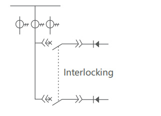
| Instruction | ≤11KW | ≤37KW | ≤75KW | Electric interlocking automatic or manual switch | ||||||||
| According to each cabinet circuit number,
the appliance should consider the heating capacity * adopt current transformer protection. |
||||||||||||
| Program No. | 20 | 21 | 22 | ||
| Single line diagram | 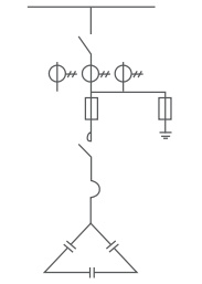 |
||||
| Application | 6 Loops power compensation | 8 Loops power compensation | 10 Loops power compensation | ||
| Knife fuse switch | QSA400 | QSA400 | QSA400 | QSA400(630) | |
| Fuse | NT00 | NT00 | NT00 | NT00 | |
| ctri
ents |
Contactor | Cj19 | Cj19 | Cj19 | Cj19 |
| ele
pon |
Capacitor | BSMJ0.415-20-3 | BSMJ0.415-20-3 | BSMJ0.415-20-3 | BSMJ0.415-20-3 |
| om |
Reactive power compensation |
JKL | JKL | JKL | JKL |
| c | Current transformer | LMK-0.66 | LMK-0.66 | LMK-0.66 | LMK-0.66 |
| Surge arrester | FYS-0.22 | FYS-0.22 | FYS-0.22 | FYS-0.22 | |
| Cabinet width(mm) | 600 | 800 | 800 | 800(1000) | |
| Small compartment height(mm) | 1800 | 1800 | 1800 | 1800 | |
| Instruction | When used for auxiliary cabinet, eliminate the reactive compensator Automatic switching is controlled by main cabinet | ||||

Related Products
-
 XL Low Voltage Power Distribution CabinetSelection Operating conditions 1. Environmental Conditions1.Installation Site: Indoor; 2. Altitude: No more than 2000m. 3. Earthquake lntensity: No more than 8 degrees. 4. Ambient Temperature: No more than +40℃ and no less than -15℃ . Averagetemperature is no more than +35℃ within 24 hours. 5. Relative Humidity: the average daily value is no more than 95%, the averagemonthly value is no more than 90%. 6. Installation locations: without fire,explosion danger,serious pollution,chemical corros...
 -
 JXF Low-voltage Integrated Distribution BoxSelection Operating conditions 1. Installation Site: Indoor or outdoor; 2. Atitude: No more than 2000m. 3. Earthquake lntensity: No more than 8 degrees. 4. Ambient Temperature: No more than +40℃ and no less than -25℃.Averagetemperature is no more than +35℃ within 24 hours. 5. Relative Humidity: the average daily value is no more than 95%, the averagemonthly value is no more than 90%. 6. Installation locations: without fire,explosion danger,serious pollution,chemical corrosion and violent vi...
 -
 GGD Low Voltage Power Distribution CabinetSelection Operating conditions 1. Ambient air temperature: -15℃ ~+40℃ Daily average temperature: ≤35℃ When the actual temperature exceed the range, it should be used by reducing the capacity accordingly. 2. Transport and store temperature: -25℃ ~+55℃ . do not exceed +70℃ in short time. 3. Altitude: ≤2000m 4. Relative humidity: ≤50%, when temperature is +40℃ When temperature is low, larger relative humidity is allowed. when it is +20℃, relative humidity can be 90%. Since the temperature chang...
 -
 MNS Low-voltage Switchgear Panel, Withdrawable ...Selection Operating conditions 1. lnstallation Site: Indoor; 2. Altitude: No more than 2000m. 3. Earthquake lntensity: No more than 8 degrees. 4. Ambient Temperature: No more than +40℃ and no less than -15℃.Averagetemperature is no more than +35℃ within 24 hours. 5. Pelative Humidity: the average daily value is no more than 95%, the averagemonthlyvalue is no more than 90%. 6. Installation lacations: without fire,explosion danger,serious pollution,chemical corrosion and violent vibration. Fe...
 -
 GCS Low-voltage Switchgear Panel, Withdrawable ...Selection Operating conditions 1. Ambient air temperature: -15℃ ~+40℃ Daily average temperature: ≤35℃ When the actual temperature exceed the range, it should be used by reducing the capacity accordingly. 2. Altitude: ≤2000m 3. Relative humidity: ≤50%, when temperature is +40℃ When temperature is low, larger relative humidity is allowed. when it is +20℃, relative humidity can be 90%. Since the temperature change will make out condensation. 4. Installation inclination: ≤5% 5. Applicable in the...


-
Phone:86-577-6289 8809
-
Email:cncele@cncele.com
-
Address:CNC High-Tech Hutou Industrial Zone, Liushi Town,Yueqing . Wenzhou City, China


Sitemap - AMP Mobile
outdoor prefabricated substation, current transformer manufacturers, current transformer cost, Current Transformer, china prefabricated outdoor substation, prefabricated outdoor substation,